Bosch originally developed the Controller Area Network (CAN) in 1985 for in-vehicle networks. In the past, automotive manufacturers connected electronic devices in vehicles using point-to-point wiring systems. Manufacturers began using more and more electronics in vehicles, which resulted in bulky wire harnesses that were heavy and expensive. They then replaced dedicated wiring with in-vehicle networks, which reduced wiring cost, complexity, and weight. CAN, a high-integrity serial bus system for networking intelligent devices, emerged as the standard in-vehicle network. The automotive industry quickly adopted CAN and, in 1993, it became the international standard known as ISO 11898. Since 1994, several higher-level protocols have been standardized on CAN, such as CANopen and DeviceNet. Other markets have widely adopted these additional protocols, which are now standards for industrial communications. This white paper focuses on CAN as an in-vehicle network.
2. CAN Benefits
Low-Cost, Lightweight Network CAN provides an inexpensive, durable network that helps multiple CAN devices communicate with one another. An advantage to this is that electronic control units (ECUs) can have a single CAN interface rather than analog and digital inputs to every device in the system. This decreases overall cost and weight in automobiles.
Broadcast CommunicationEach of the devices on the network has a CAN controller chip and is therefore intelligent. All devices on the network see all transmitted messages. Each device can decide if a message is relevant or if it should be filtered. This structure allows modifications to CAN networks with minimal impact. Additional non-transmitting nodes can be added without modification to the network.
PriorityEvery message has a priority, so if two nodes try to send messages simultaneously, the one with the higher priority gets transmitted and the one with the lower priority gets postponed. This arbitration is non-destructive and results in non-interrupted transmission of the highest priority message. This also allows networks to meet deterministic timing constraints.
Error CapabilitiesThe CAN specification includes a Cyclic Redundancy Code (CRC) to perform error checking on each frame’s contents. Frames with errors are disregarded by all nodes, and an error frame can be transmitted to signal the error to the network. Global and local errors are differentiated by the controller, and if too many errors are detected, individual nodes can stop transmitting errors or disconnect itself from the network completely.
Figure 1. CAN networks significantly reduce wiring.
3. CAN Applications
CAN was first created for automotive use, so its most common application is in-vehicle electronic networking. However, as other industries have realized the dependability and advantages of CAN over the past 20 years, they have adopted the bus for a wide variety of applications. Railway applications such as streetcars, trams, undergrounds, light railways, and long-distance trains incorporate CAN. You can find CAN on different levels of the multiple networks within these vehicles – for example, in linking the door units or brake controllers, passenger counting units, and more. CAN also has applications in aircraft with flight-state sensors, navigation systems, and research PCs in the cockpit. In addition, you can find CAN buses in many aerospace applications, ranging from in-flight data analysis to aircraft engine control systems such as fuel systems, pumps, and linear actuators.
Medical equipment manufacturers use CAN as an embedded network in medical devices. In fact, some hospitals use CAN to manage complete operating rooms. Hospitals control operating room components such as lights, tables, cameras, X-ray machines, and patient beds with CAN-based systems. Lifts and escalators use embedded CAN networks, and hospitals use the CANopen protocol to link lift devices, such as panels, controllers, doors, and light barriers, to each other and control them. CANopen also is used in nonindustrial applications such as laboratory equipment, sports cameras, telescopes, automatic doors, and even coffee machines.
4. CAN Physical Layers
CAN has several different physical layers you can use. These physical layers classify certain aspects of the CAN network, such as electrical levels, signaling schemes, cable impedance, maximum baud rates, and more. The most common and widely used physical layers are described below:
High-Speed/FD CAN High-speed CAN is by far the most common physical layer. High-speed CAN networks are implemented with two wires and allow communication at transfer rates up to 1 Mbit/s. Other names for high-speed CAN include CAN C and ISO 11898-2. Typical high-speed CAN devices include antilock brake systems, engine control modules, and emissions systems. CAN with Flexible Data-Rate (CAN FD) is the next generation of high-speed CAN communication with evolving standards for higher data rates. NI has enabled speeds up to 8 Mbit/s using the TJA1041 and TJA1043 transceivers through the NI-XNET driver. As transceiver vendors complete qualifications for CAN FD speeds, NI will update our documentation as necessary.
Low-Speed/Fault-Tolerant CAN Hardware Low-speed/fault-tolerant CAN networks are also implemented with two wires, can communicate with devices at rates up to 125 kbit/s, and offer transceivers with fault-tolerant capabilities. Other names for low-speed/fault-tolerant CAN include CAN B and ISO 11898-3. Typical low-speed/fault-tolerant devices in an automobile include comfort devices. Wires that have to pass through the door of a vehicle are low-speed/fault-tolerant in light of the stress that is inherent to opening and closing a door. Also, in situations where an advanced level of security is desired, such as with brake lights, low-speed/fault-tolerant CAN offers a solution.
Single-Wire CAN Hardware Single-wire CAN interfaces can communicate with devices at rates up to 33.3 kbit/s (88.3 kbit/s in high-speed mode). Other names for single-wire CAN include SAE-J2411, CAN A, and GMLAN. Typical single-wire devices within an automobile do not require high performance. Common applications include comfort devices such as seat and mirror adjusters.
Software-Selectable CAN Hardware With National Instruments CAN hardware products, you can configure the software-selectable CAN interfaces to use any of the onboard transceivers (high-speed, low-speed/fault-tolerant, or single-wire CAN). Multiple-transceiver hardware offers the perfect solution for applications that require a combination of communications standards. With software-selectable CAN hardware, you also can choose your own external CAN transceiver.
5. CAN Terminology
CAN devices send data across the CAN network in packets called frames. A CAN frame consists of the following sections.
CAN Frame— an entire CAN transmission: arbitration ID, data bytes, acknowledge bit, and so on. Frames also are referred to as messages.
Figure 2. The standard CAN frame format.
SOF (start-of-frame) bit – indicates the beginning of a message with a dominant (logic 0) bit.
Arbitration ID – identifies the message and indicates the message’s priority. Frames come in two formats — standard, which uses an 11-bit arbitration ID, and extended, which uses a 29-bit arbitration ID.
IDE(identifier extension) bit – allows differentiation between standard and extended frames.
RTR (remote transmission request) bit – serves to differentiate a remote frame from a data frame. A dominant (logic 0) RTR bit indicates a data frame. A recessive (logic 1) RTR bit indicates a remote frame.
DLC(data length code) – indicates the number of bytes the data field contains.
Data Field – contains 0 to 8 bytes of data.
CRC (cyclic redundancy check) – contains 15-bit cyclic redundancy check code and a recessive delimiter bit. The CRC field is used for error detection.
ACK(ACKnowledgement) slot – any CAN controller that correctly receives the message sends an ACK bit at the end of the message. The transmitting node checks for the presence of the ACK bit on the bus and reattempts transmission if no acknowledge is detected. National Instruments Series 2 CAN interfaces have the capability of listen-only mode. Herein, the transmission of an ACK bit by the monitoring hardware is suppressed to prevent it from affecting the behavior of the bus.
CAN Signal – an individual piece of data contained within the CAN frame data field. You also can refer to CAN signals as channels. Because the data field can contain up to 8 bytes of data, a single CAN frame can contain 0 to 64 individual signals (for 64 channels, they would all be binary).
In the following image, there are six channels contained in the data field of a single CAN frame. Each signal contains 8 bits of data.
Figure 3. Signals can be defined as a certain number of bits inside of a CAN frame.
CAN database files are text files that contain scaling information for CAN frames and signal definitions. National Instruments NI-XNET database editor software recognizes FIBEX database files (.xml), Vector database files (*.dbc), and National Instruments CAN database files (*.ncd).
For each signal, CAN databases define rules for conversion to engineering units. The following data is stored in databases:
Channel name
Location (start bit) and size (number of bits) of the channel within a given message
Byte order (Intel/Motorola)
Data type (signed, unsigned, and IEEE float)
Scaling and units string
Range
Default value
Comment
You can use this information to easily convert the “raw” frame information (usually bytes) to a “real world” value. The picture below illustrates an example of this conversion.
Figure 4. All of the necessary scaling data is contained in a database for converting frames to signals.
CAN database files may contain frame and signal definitions for an entire vehicle. Every network has its own unique database file. Additionally, these database files are vendor-specific and usually confidential.
By using a database file for many frames on the CAN network, many CAN APIs (like NI-XNET) can automatically convert the frame information directly to a real-world value. This simplifies application development because you never need to worry about the raw frame values.
7. How CAN Communication Works
As stated earlier, CAN is a peer-to-peer network. This means that there is no master that controls when individual nodes have access to read and write data on the CAN bus. When a CAN node is ready to transmit data, it checks to see if the bus is busy and then simply writes a CAN frame onto the network. The CAN frames that are transmitted do not contain addresses of either the transmitting node or any of the intended receiving node(s). Instead, an arbitration ID that is unique throughout the network labels the frame. All nodes on the CAN network receive the CAN frame, and, depending on the arbitration ID of that transmitted frame, each CAN node on the network decides whether to accept the frame.
If multiple nodes try to transmit a message onto the CAN bus at the same time, the node with the highest priority (lowest arbitration ID) automatically gets bus access. Lower-priority nodes must wait until the bus becomes available before trying to transmit again. In this way, you can implement CAN networks to ensure deterministic communication among CAN nodes.
Figure 5. CAN contains built in priority for messages to avoid conflicts.
CAN data link layers in some detail
The CAN data link layer comprises two protocols: Classical CAN introduced in 1986 and implemented for the first time in 1988 and CAN FD launched in 2012 and internationally standardized in 2015 in ISO 11898-1. For a transitional period there are also non-ISO compliant implementations on the market. They are application-transparent, meaning they can be used for software development and designing prototype networks. However, CiA doesn’t recommend using them for serial production.
The structure of CAN data frames are the same for Classical CAN and CAN FD, just the field details are different
The two CAN data link layer protocols have some common features. Any node has the right to request transmission rights at any time. The necessary bus arbitration method to avoid transmission conflicts is the same: Frames with the highest assigned identifier get bus access without delay. All frame types (data, remote, error, and overload frame) are transmitted in broadcast. The data frame structure comprising several fields is the same.
One of the unique features of the CAN data link layers is that all single-bit errors are detected. Multi-bit errors are detected with a high probability. In order to provide data consistency in all nodes, local errors are globalized. Additionally, the fault confinement implemented in the CAN data link layers precludes a single node from corrupting the communication of the others permanently.
The Classical CAN protocol uses just one bit-rate in the arbitration and the data phase. The transmission speed is limited to 1 Mbit/s for short networks (theoretically up to 40 m). However the achievable bit-rate depends on the network length and the used physical layer elements such as cable, connector, and transceiver. The payload, the data field, is limited to 8 byte.
The CAN FD protocol allows payloads up to 64 byte. Additionally, it supports an optional second bit-rate for the data-phase. The limitation of the speed in the arbitration phase is the same as for Classical CAN. In the data phase, the speed is limited by transceiver characteristic, the oscillator tolerance, and the topology (ringing). Data phase bit rates up to 8 Mbit/s are realistic when using a bus-line topology with very short, not terminated stubs.
Data (and remote) frame structure
The data frames in Classical CAN and CAN FD comprises the same fields. The remote frame, only available in Classical CAN, has the same field structure as the data frame, but without a data field.
The Classical CAN and CAN FD frame formats differ mainly in the control field: At the sample point of the BRS bit the bit-rate is changed
The SOF (start-of-frame) field is a fixed 1-bit field with a dominant bit level. It is followed by the arbitration field, which contains mainly the identifier bits and some protocol bits indicating the length of the CAN-ID and reserved bits. The next field is the control field with the information on the length of the data field (four data length code bits). Additionally, it provides some control bits, e.g. the FDF (FD format) bit distinguishing the two data link layer protocols, Classical CAN and CAN FD. The payload is in the data field. In Classical CAN, it features up to 8 byte and in CAN FD it can be up to 64 byte long. The following CRC field comprises a cyclic redundancy checksum (CRC) and in CAN FD an additional stuff-bit counter. The ACK (acknowledge) field is made of two bits. It is used to indicate a correct reception of the message. The last fields are the 7-bit EOF (end-of-fame) with fixed format (recessive bit-level) and the 3-bit IMF (intermission field) separating the frame from the next one.
Data (and remote) frame formats
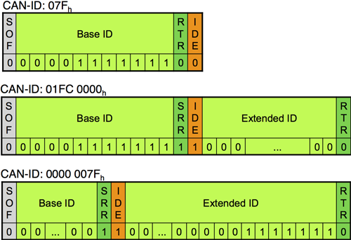
The CAN data link layers distinguish between base frames (11-bit CAN-ID) and extended frames (29-bit CAN-ID). Base frames have a dominant IDE (ID extension) bit. This is why they win bus-arbitration against extended frames with the very same first bit-pattern. In order to distinguish between Classical CAN and CAN FD frames, the r1 reserved bit is transmitted recessively in CAN FD frames. Of course, this violates the Classical CAN specification. This means that legacy CAN controller chips destroy CAN FD communication. However, there are some migration paths that let you use legacy CAN implementations in CAN FD networks.
In the shown Classical CAN arbitration field examples, “0” represents a dominant and “1” a recessive bus-level (ID = identifier, SOF = start-of-frame, RTR= remote transmission request, SRR = substitute remote request, IDE = identifier extension)
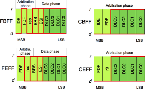
The ISO 11898-1 standard introduces four different formats:
CBFF: Classical base frame format with 11-bit IDs
CEFF: Classical extended frame format with 29-bit IDs
FBFF: FD base frame format with 11-bit IDs
FEFF: FD extended frame format with 29-bit IDs
The formats differ in the control field (additional bits in FD frames), the data field length (Classical data frames are limited to a maximum of 8 byte, while FD data frames allow up to 64 byte), and the CRC field (different polynomials and additional safeguards for FD frames). Remote frames are not supported by the CAN FD protocol. CiA doesn’t recommend using remote frames. Remote frames request a data frame with the very same CAN-ID.
 Figure 1. CAN networks significantly reduce wiring.
 Figure 2. The standard CAN frame format.

 Figure 4. All of the necessary scaling data is contained in a database for converting frames to signals.
CAN database files may contain frame and signal definitions for an entire vehicle. Every network has its own unique database file. Additionally, these database files are vendor-specific and usually confidential.
By using a database file for many frames on the CAN network, many CAN APIs (like NI-XNET) can automatically convert the frame information directly to a real-world value. This simplifies application development because you never need to worry about the raw frame values.
Figure 4. All of the necessary scaling data is contained in a database for converting frames to signals.
CAN database files may contain frame and signal definitions for an entire vehicle. Every network has its own unique database file. Additionally, these database files are vendor-specific and usually confidential.
By using a database file for many frames on the CAN network, many CAN APIs (like NI-XNET) can automatically convert the frame information directly to a real-world value. This simplifies application development because you never need to worry about the raw frame values.
 Figure 5. CAN contains built in priority for messages to avoid conflicts.
 The structure of CAN data frames are the same for Classical CAN and CAN FD, just the field details are different
The two CAN data link layer protocols have some common features. Any node has the right to request transmission rights at any time. The necessary bus arbitration method to avoid transmission conflicts is the same: Frames with the highest assigned identifier get bus access without delay. All frame types (data, remote, error, and overload frame) are transmitted in broadcast. The data frame structure comprising several fields is the same.
One of the unique features of the CAN data link layers is that all single-bit errors are detected. Multi-bit errors are detected with a high probability. In order to provide data consistency in all nodes, local errors are globalized. Additionally, the fault confinement implemented in the CAN data link layers precludes a single node from corrupting the communication of the others permanently.
The Classical CAN protocol uses just one bit-rate in the arbitration and the data phase. The transmission speed is limited to 1 Mbit/s for short networks (theoretically up to 40 m). However the achievable bit-rate depends on the network length and the used physical layer elements such as cable, connector, and transceiver. The payload, the data field, is limited to 8 byte.
The CAN FD protocol allows payloads up to 64 byte. Additionally, it supports an optional second bit-rate for the data-phase. The limitation of the speed in the arbitration phase is the same as for Classical CAN. In the data phase, the speed is limited by transceiver characteristic, the oscillator tolerance, and the topology (ringing). Data phase bit rates up to 8 Mbit/s are realistic when using a bus-line topology with very short, not terminated stubs.
The structure of CAN data frames are the same for Classical CAN and CAN FD, just the field details are different
The two CAN data link layer protocols have some common features. Any node has the right to request transmission rights at any time. The necessary bus arbitration method to avoid transmission conflicts is the same: Frames with the highest assigned identifier get bus access without delay. All frame types (data, remote, error, and overload frame) are transmitted in broadcast. The data frame structure comprising several fields is the same.
One of the unique features of the CAN data link layers is that all single-bit errors are detected. Multi-bit errors are detected with a high probability. In order to provide data consistency in all nodes, local errors are globalized. Additionally, the fault confinement implemented in the CAN data link layers precludes a single node from corrupting the communication of the others permanently.
The Classical CAN protocol uses just one bit-rate in the arbitration and the data phase. The transmission speed is limited to 1 Mbit/s for short networks (theoretically up to 40 m). However the achievable bit-rate depends on the network length and the used physical layer elements such as cable, connector, and transceiver. The payload, the data field, is limited to 8 byte.
The CAN FD protocol allows payloads up to 64 byte. Additionally, it supports an optional second bit-rate for the data-phase. The limitation of the speed in the arbitration phase is the same as for Classical CAN. In the data phase, the speed is limited by transceiver characteristic, the oscillator tolerance, and the topology (ringing). Data phase bit rates up to 8 Mbit/s are realistic when using a bus-line topology with very short, not terminated stubs.
No comments:
Post a Comment