LIQUID CRYSTAL DISPLAY:
LCD (Liquid Crystal Display) screen is an electronic display module and find a wide range of applications. A 16x2 LCD display is very basic module and is very commonly used in various devices and circuits. These modules are preferred over seven segments and other multi segment LEDs. The reasons being: LCDs are economical; easily programmable; have no limitation of displaying special & even custom characters (unlike in seven segments), animations and so on.
A 16x2 LCD means it can display 16 characters per line and there are 2 such lines. In this LCD each character is displayed in 5x7 pixel matrix. This LCD has two registers, namely, Command and Data. The command register stores the command instructions given to the LCD. A command is an instruction given to LCD to do a predefined task like initializing it, clearing its screen, setting the cursor position, controlling display etc. The data register stores the data to be displayed on the LCD. The data is the ASCII value of the character to be displayed on the LCD.

LCD stands for Liquid Crystal Display. LCD is finding wide spread use replacing LEDs (seven segment LEDs or other multi segment LEDs) because of the following reasons:
1. The declining prices of LCDs.
2. The ability to display numbers, characters and graphics. This is in contrast to LEDs, which are limited to numbers and a few characters.
3. Incorporation of a refreshing controller into the LCD, thereby relieving the CPU of the task of refreshing the LCD. In contrast, the LED must be refreshed by the CPU to keep displaying the data.
4. Ease of programming for characters and graphics.
These components are “specialized” for being used with the microcontrollers, which means that they cannot be activated by standard IC circuits. They are used for writing different messages on a miniature LCD.
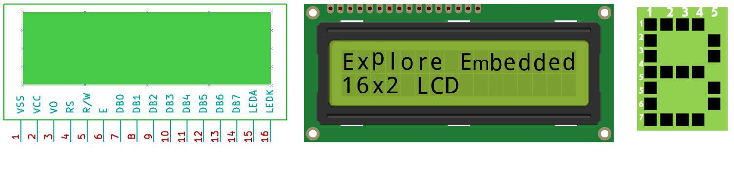
Fig 6.3 LCD display
A model as shown in figure 6.3 here is for its low price and great possibilities most frequently used in practice. It is based on the HD44780 microcontroller (Hitachi) and can display messages in two lines with 16 characters each. It displays all the alphabets, Greek letters, punctuation marks, mathematical symbols etc. In addition, it is possible to display symbols that user makes up on its own. Automatic shifting message on display (shift left and right), appearance of the pointer, backlight etc. are considered as useful characteristics.
Pins Functions
There are pins along one side of the small printed board used for connection to the microcontroller. There are total of 14 pins marked with numbers (16 in case the background light is built in). Their function is described in the table 6.1 below:
Function
|
Pin Number
|
Name
|
Logic State
|
Description
|
Ground
|
1
|
Vss
|
-
|
0V
|
Power supply
|
2
|
Vdd
|
-
|
+5V
|
Contrast
|
3
|
Vee
|
-
|
0 – Vdd
|
Control of operating
|
4
|
RS
|
0
1 |
D0 – D7 are interpreted as commands
D0 – D7 are interpreted as data |
5
|
R/W
|
0
1 |
Write data (from controller to LCD)
Read data (from LCD to controller) | |
6
|
E
|
0
1 From 1 to 0 |
Access to LCD disabled
Normal operating Data/commands are transferred to LCD | |
Data / commands
|
7
|
D0
|
0/1
|
Bit 0 LSB
|
8
|
D1
|
0/1
|
Bit 1
| |
9
|
D2
|
0/1
|
Bit 2
| |
10
|
D3
|
0/1
|
Bit 3
| |
11
|
D4
|
0/1
|
Bit 4
| |
12
|
D5
|
0/1
|
Bit 5
| |
13
|
D6
|
0/1
|
Bit 6
| |
14
|
D7
|
0/1
|
Bit 7 MSB
|
Table 6.1 pin description of LCD
LCD screen:
LCD screen consists of two lines with 16 characters each. Each character consists of 5x7 dot matrix. Contrast on display depends on the power supply voltage and whether messages are displayed in one or two lines. For that reason, variable voltage 0-Vdd is applied on pin marked as Vee. Trimmer potentiometer is usually used for that purpose the connections are as shown in figure 6.4. Some versions of displays have built in backlight (blue or green diodes). When used during operating, a resistor for current limitation should be used (like with any LE diode).
Fig 6.4:power supply connection to LCD
LCD Basic Commands
All data transferred to LCD through outputs D0-D7 will be interpreted as commands or as data, which depends on logic state on pin RS:
Ø RS = 1 - Bits D0 - D7 are addresses of characters that should be displayed. Built in processor addresses built in “map of characters” and displays corresponding symbols. Displaying position is determined by DDRAM address. This address is either previously defined or the address of previously transferred character is automatically incremented.
Ø RS = 0 - Bits D0 - D7 are commands which determine display mode. List of commands which LCD recognizes are given in the table 6.2 below:
Command
|
RS
|
RW
|
D7
|
D6
|
D5
|
D4
|
D3
|
D2
|
D1
|
D0
|
Execution Time
|
Clear display
|
0
|
0
|
0
|
0
|
0
|
0
|
0
|
0
|
0
|
1
|
1.64mS
|
Cursor home
|
0
|
0
|
0
|
0
|
0
|
0
|
0
|
0
|
1
|
x
|
1.64mS
|
Entry mode set
|
0
|
0
|
0
|
0
|
0
|
0
|
0
|
1
|
I/D
|
S
|
40uS
|
Display on/off control
|
0
|
0
|
0
|
0
|
0
|
0
|
1
|
D
|
U
|
B
|
40uS
|
Cursor/Display Shift
|
0
|
0
|
0
|
0
|
0
|
1
|
D/C
|
R/L
|
X
|
x
|
40uS
|
Function set
|
0
|
0
|
0
|
0
|
1
|
DL
|
N
|
F
|
X
|
x
|
40uS
|
Set CGRAM address
|
0
|
0
|
0
|
1
|
CGRAM address
|
40uS
| |||||
Set DDRAM address
|
0
|
0
|
1
|
DDRAM address
|
40uS
| ||||||
Read “BUSY” flag (BF)
|
0
|
1
|
BF
|
DDRAM address
|
-
| ||||||
Write to CGRAM or DDRAM
|
1
|
0
|
D7
|
D6
|
D5
|
D4
|
D3
|
D2
|
D1
|
D0
|
40uS
|
Read from CGRAM or DDRAM
|
1
|
1
|
D7
|
D6
|
D5
|
D4
|
D3
|
D2
|
D1
|
D0
|
40uS
|
Function
|
Value
|
Operation
|
I/D
|
1
|
Increment by 1
|
0
|
Decrement by 1
| |
S
|
1
|
Display shift on
|
0
|
Display shift off
| |
D
|
1
|
Display on
|
0
|
Display off
| |
U
|
1
|
Cursor on
|
0
|
Cursor off
| |
B
|
1
|
Cursor blink on
|
0
|
Cursor blink off
| |
R/L
|
1
|
Shift right
|
0
|
Shift left
| |
DL
|
1
|
8-bit interface
|
0
|
4-bit interface
| |
N
|
1
|
Display in two lines
|
0
|
Display in one line
| |
F
|
1
|
Character format 5x10 dots
|
0
|
Character format 5x7 dots
| |
D/C
|
1
|
Display shift
|
0
|
Cursor shift
|
Table 6.2: LCD command description
LCD Connection
Depending on how many lines are used for connection to the microcontroller, there are 8-bit and 4-bit LCD modes. The appropriate mode is determined at the beginning of the process in a phase called “initialization”. In the first case, the data are transferred through outputs D0-D7 as it has been already explained. In case of 4-bit LED mode, for the sake of saving valuable I/O pins of the microcontroller, there are only 4 higher bits (D4-D7) used for communication, while other may be left unconnected.
Consequently, each data is sent to LCD in two steps: four higher bits are sent first (that normally would be sent through lines D4-D7), four lower bits are sent afterwards. With the help of initialization, LCD will correctly connect and interpret each data received. Besides, with regards to the fact that data are rarely read from LCD (data mainly are transferred from microcontroller to LCD) one more I/O pin may be saved by simple connecting R/W pin to the Ground. Even though message displaying will be normally performed, it will not be possible to read from busy flag since it is not possible to read from display.
LCD Initialization
Once the power supply is turned on, LCD is automatically cleared. This process lasts for approximately 15mS. After that, display is ready to operate. The mode of operating is set by default. This means that:
1. Display is cleared
2. Mode
DL = 1 Communication through 8-bit interface
N = 0 Messages are displayed in one line
F = 0 Character font 5 x 8 dots
3. Display/Cursor on/off
D = 0 Display off
U = 0 Cursor off
B = 0 Cursor blink off
4. Character entry
ID = 1 Addresses on display are automatically incremented by 1
S = 0 Display shift off
Automatic reset is mainly performed without any problems. If for any reason power supply voltage does not reach full value in the course of 10mS, display will start perform completely unpredictably. If voltage supply unit can not meet this condition or if it is needed to provide completely safe operating, the process of initialization by which a new reset enabling display to operate normally must be applied.
Algorithm according to the initialization is being performed depends on whether connection to the microcontroller is through 4- or 8-bit interface. All left over to be done after that is to give basic commands and of course- to display messages. The algorithm is as shown in the figure 6.5
Fig 6.5 algorithm for initialization of 8-bit LCD
Contrast Control:
To have a clear view of the characters on the LCD, contrast should be adjusted. To adjust the contrast, the voltage should be varied. For this, a preset is used which can behave like a variable voltage device. As the voltage of this preset is varied, the contrast of the LCD can be adjusted.
Potentiometer
Variable resistors used as potentiometers have all three terminalsconnected. This arrangement is normally used to vary voltage, for example to set the switching point of a circuit with a sensor, or control the volume (loudness) in an amplifier circuit. If the terminals at the ends of the track are connected across the power supply, then the wiper terminal will provide a voltage which can be varied from zero up to the maximum of the supply.
No comments:
Post a Comment