POTENTIOMETER
A potentiometer is a manually adjustable electrical resistor that uses three terminals. It is a simple electro-mechanical transducer. It converts rotary or linear motion from the operator into a change of resistance, and this change is used to control the levels of output. It is sometimes known as POTS.
For example, in a loudspeaker, a potentiometer is used to adjust the volume. In a television set, computer monitor or light dimmer, it can be used to control the brightness of the screen or light bulb.
WORKING OF A POTENTIOMETER
In a potentiometer an electrically conductive wiper slides across a fixed resistive element.
One terminal of the potentiometer is connected to a power source, and another is hooked up to a ground — a point with no voltage or resistance and which serves as a neutral reference point. The third terminal slides across a strip of resistive material. This resistive strip generally has a low resistance at one end, and its resistance gradually increases to a maximum resistance at the other end. The third terminal serves as the connection between the power source and ground, and it usually is operated by the user through the use of a knob or lever.
The user can adjust the position of the third terminal along the resistive strip to manually increase or decrease resistance. The amount of resistance determines how much current flows through a circuit.The output voltage is proportional to the distance travelled.
CIRCUIT SYMBOL

TYPES OF POTENTIOMETER
There are two types of potentiometer, linear and rotary potentiometer.
The linear potentiometer has a slide or wiper. The rotary potentiometer can be a single turn or multi turn.
Digital Potentiometers
A digital potentiometer adjusts and trims electronic circuits similar to variable resistors, rheostats and mechanical potentiometers. Sometimes called digital POT, RDAC, or digipot, these compact devices can be used to calibrate system tolerances or dynamically control system parameters.
The parameters while selecting a potentiometer:
•Operating temperature
•Shock and vibration
•Humidity
•Contamination and seals
ADVANTAGES
•Easy to use
•low cost
•High amplitude output
•Easily available
DISADVANTAGES
•Friction problem
•Limited bandwidth
•Inertial loading
APPLICATIONS
•Linear displacement measurement
•Rotary displacement measurement
•Volume control
•Brightness control
•Liquid level measurements using floats
Operational Problems with the Potentiometers
Resistance–position relationship: "taper"
Linear taper potentiometer
Logarithmic potentiometer
A potentiometer is a manually adjustable electrical resistor that uses three terminals. It is a simple electro-mechanical transducer. It converts rotary or linear motion from the operator into a change of resistance, and this change is used to control the levels of output. It is sometimes known as POTS.
For example, in a loudspeaker, a potentiometer is used to adjust the volume. In a television set, computer monitor or light dimmer, it can be used to control the brightness of the screen or light bulb.
WORKING OF A POTENTIOMETER
In a potentiometer an electrically conductive wiper slides across a fixed resistive element.
One terminal of the potentiometer is connected to a power source, and another is hooked up to a ground — a point with no voltage or resistance and which serves as a neutral reference point. The third terminal slides across a strip of resistive material. This resistive strip generally has a low resistance at one end, and its resistance gradually increases to a maximum resistance at the other end. The third terminal serves as the connection between the power source and ground, and it usually is operated by the user through the use of a knob or lever.
The user can adjust the position of the third terminal along the resistive strip to manually increase or decrease resistance. The amount of resistance determines how much current flows through a circuit.The output voltage is proportional to the distance travelled.
CIRCUIT SYMBOL
TYPES OF POTENTIOMETER
There are two types of potentiometer, linear and rotary potentiometer.
The linear potentiometer has a slide or wiper. The rotary potentiometer can be a single turn or multi turn.
Digital Potentiometers
A digital potentiometer adjusts and trims electronic circuits similar to variable resistors, rheostats and mechanical potentiometers. Sometimes called digital POT, RDAC, or digipot, these compact devices can be used to calibrate system tolerances or dynamically control system parameters.
The parameters while selecting a potentiometer:
•Operating temperature
•Shock and vibration
•Humidity
•Contamination and seals
ADVANTAGES
•Easy to use
•low cost
•High amplitude output
•Easily available
DISADVANTAGES
•Friction problem
•Limited bandwidth
•Inertial loading
APPLICATIONS
•Linear displacement measurement
•Rotary displacement measurement
•Volume control
•Brightness control
•Liquid level measurements using floats
Potentiometers comprise a resistive element, a sliding contact (wiper) that moves along the element, making good electrical contact with one part of it, electrical terminals at each end of the element, a mechanism that moves the wiper from one end to the other, and a housing containing the element and wiper.
Many inexpensive potentiometers are constructed with a resistive element formed into an arc of a circle usually a little less than a full turn, and a wiper rotating around the arc and contacting it. The resistive element, with a terminal at each end, is flat or angled. The wiper is connected to a third terminal, usually between the other two. On panel potentiometers, the wiper is usually the center terminal of three. For single-turn potentiometers, this wiper typically travels just under one revolution around the contact. The only point of ingress for contamination is the narrow space between the shaft and the housing it rotates in.
Another type is the linear slider potentiometer, which has a wiper which slides along a linear element instead of rotating. Contamination can potentially enter anywhere along the slot the slider moves in, making effective sealing more difficult and compromising long-term reliability. An advantage of the slider potentiometer is that the slider position gives a visual indication of its setting. While the setting of a rotary potentiometer can be seen by the position of a marking on the knob, an array of sliders can give a visual impression of, for example, the effect of a multi-band equaliser.
The resistive element of inexpensive potentiometers is often made of graphite. Other materials used include resistance wire, carbon particles in plastic, and a ceramic/metal mixture called cermet. Conductive track potentiometers use conductive polymer resistor pastes that contain hard-wearing resins and polymers, solvents, and lubricant, in addition to the carbon that provides the conductive properties. Others are enclosed within the equipment and are intended to be adjusted to calibrate equipment during manufacture or repair, and not otherwise touched. They are usually physically much smaller than user-accessible potentiometers, and may need to be operated by a screwdriver rather than having a knob. They are usually called "preset potentiometers" or "trim[ming] pots". Some presets are accessible by a small screwdriver poked through a hole in the case to allow servicing without dismantling.
Multiturn potentiometers are also operated by rotating a shaft, but by several turns rather than less than a full turn. Some multiturn potentiometers have a linear resistive element with a sliding contact moved by a lead screw; others have a helical resistive element and a wiper that turns through 10, 20, or more complete revolutions, moving along the helix as it rotates. Multiturn potentiometers, both user-accessible and preset, allow finer adjustments; rotation through the same angle changes the setting by typically a tenth as much as for a simple rotary potentiometer.
A string potentiometer is a multi-turn potentiometer operated by an attached reel of wire turning against a spring, enabling it to convert linear position to a variable resistance.
User-accessible rotary potentiometers can be fitted with a switch which operates usually at the anti-clockwise extreme of rotation. Before digital electronics became the norm such a component was used to allow radio and television receivers and other equipment to be switched on at minimum volume with an audible click, then the volume increased, by turning a knob. Multiple resistance elements can be ganged together with their sliding contacts on the same shaft, for example, in stereo audio amplifiers for volume control.
Types of Potentiometers
There are three types of potentiometers that are used commonly: wire wound, carbon film and plastic film potentiometers. All these have been described below:
1) Wire wound potentiometers: This potentiometer comprises of several rounds of wire wound around the shaft of the non-conducting material. The turns of the coil are bonded together by an adhesive. In this case the slider, connected to the body whose displacement is to be measured, moves on the potentiometer track and it makes contacts with successive turns of the coil. In this case the wire between the two successive turns is not covered by the slider, which limits the resolution of the wire wound potentiometers. However, the larger the number of turns of the coil, more is the resolution of the coil. The resolution is measured as the reciprocal of the number of turns of the coil. This devise has low noise and is mechanically rough and tough.
2) Carbon film potentiometers: The carbon film potentiometers are formed by depositing carbon composition ink on an insulating body, which in most of the cases is phenolic resin. This is one of the most commonly used materials for the pots that is quite cheap and has resolution better than the wire wound potentiometers. They have reasonable life and tolerable noise levels.
3) Plastic film pots: These pots comprise of the specially impregnated plastic material having resistance characteristics that are controlled properly. These can be used for rotary as well as translational slider movements. They have very good life, resolution better than the wire wound pots, and low noise.
Operational Problems with the Potentiometers
The pots are used for measurement of the displacement of the body, but some problems are associated with this measurement. These problems usually occur at the point of the contact between the slider and the resistance track. Some of these problems can be:
1) Sometimes the dirt gets accumulated between the slider and the resistance surface thus indicating more resistance than the actual value. This give false output of the voltage and in some cases there is total loss of the voltage.
2) If the slider is moved very fast there are chances that the contact will bounce which gives intermittent output of the voltage and not continuous.
3) Sometimes the friction between the slider and the resistance surface can be quite higher, which limits the movement of the slider against the actual movement of the body due to the frictional forces.
For most of the potentiometers the typical accuracy mentioned by the manufacturers is +-1% against the full scale reading of the devise. The instruments with the accuracy of +-2mm as well as +-1mm are available.
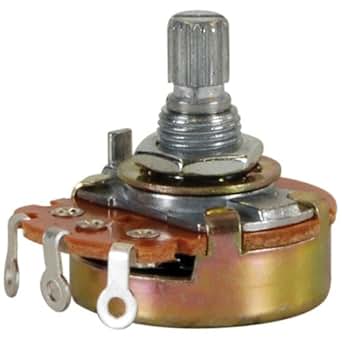
Figure below shows some commonly used pots or potentiometers.
Resistance–position relationship: "taper"
The relationship between slider position and resistance, known as the "taper" or "law", is controlled by the manufacturer. In principle any relationship is possible, but for most purposes linear or logarithmic (aka "audio taper") potentiometers are sufficient.
A letter code may be used to identify which taper is used, but the letter code definitions are not standardized. Newer potentiometers will usually be marked with an 'A' for logarithmic taper or a 'B' for linear taper. Older potentiometers may be marked with an 'A' for linear taper, a 'C' for logarithmic taper or a 'F' for anti-logarithmic taper. When a percentage is referenced with a non-linear taper, it relates to the resistance value at the midpoint of the shaft rotation. A 10% log taper would therefore measure 10% of the total resistance at the midpoint of the rotation; i.e. 10% log taper on a 10K ohm potentiometer would yield 1K at the midpoint. The higher the percentage the steeper the log curve
Linear taper potentiometer
A linear taper potentiometer (linear describes the electrical characteristic of the device, not the geometry of the resistive element) has a resistive element of constant cross-section, resulting in a device where the resistance between the contact (wiper) and one end terminal is proportional to the distance between them. Linear taper potentiometers are used when the division ratio of the potentiometer must be proportional to the angle of shaft rotation (or slider position), for example, controls used for adjusting the centering of the display on an analog cathode-ray oscilloscope. Precision potentiometers have an accurate relationship between resistance and slider position.
Logarithmic potentiometer
A logarithmic taper potentiometer has a resistive element that either 'tapers' in from one end to the other, or is made from a material whose resistivity varies from one end to the other. This results in a device where output voltage is a logarithmic function of the slider position.
Most (cheaper) "log" potentiometers are not accurately logarithmic, but use two regions of different resistance (but constant resistivity) to approximate a logarithmic law. The two resistive tracks overlap at approximately 50% of the potentiometer rotation; this gives a stepwise logarithmic taper.[3] A logarithmic potentiometer can also be simulated (not very accurately) with a linear one and an external resistor. True logarithmic potentiometers are significantly more expensive.
Logarithmic taper potentiometers are often used in connection with audio amplifiers as human perception of audio volume is logarithmic.
No comments:
Post a Comment