Introduction:
In order to save any
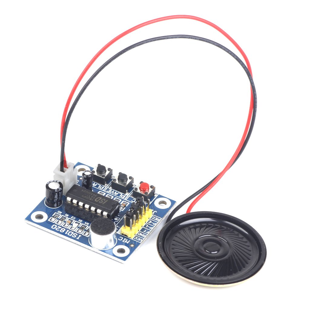
voice and play the same voice back again we have AUDIO RECORDER AND PLAY BACK module. For saving any audio signals
i.e., analog in nature we are using a Re-Recording voice IC called ARP9600. Voice
recorder and play back module which uses ARP9600 is shown below:
General
Description of ARP9600:
The APR9600 device offers true single-chip voice recording, non-volatile
storage, and playback capability for 40 to 60 seconds. The device supports both
random and sequential access of multiple messages. Sample rates are
user-selectable, allowing designers to customize their design for unique
quality and storage time needs. Integrated output amplifier, microphone amplifier,
and AGC circuits greatly simplify system design. The device is ideal for use in
portable voice recorders, toys, and many other consumer and industrial applications.
APLUS integrated achieves these high
levels of storage capability by using its proprietary
Analog/multilevel storage technology implemented in an advanced
Flash non-volatile memory process, where each memory cell can store 256 voltage
levels. This technology enables the APR9600 device to reproduce voice signals
in their natural form. It eliminates the need for encoding and compression,
which often introduce distortion.
Features:
Single-chip, high-quality voice recording & playback solution
- No external ICs required
- Minimum external components
• Non-volatile Flash memory technology
- No battery backup required
• User-Selectable messaging options
- Random access of multiple fixed-duration messages
- Sequential access of multiple variable-duration messages
• User-friendly, easy-to-use operation
- Programming & development systems not required
- Level-activated recording & edge-activated play back
switches
• Low power consumption
- Operating current: 25 mA typical
- Standby current: 1 uA typical
- Automatic power-down
• Chip Enable pin for simple message expansion
PIN DIAGRAM OF ARP9600:

FUNCTIONAL DESCRIPTION:
APR9600 block diagram is included
in order to describe the device’s internal architecture. At the left hand side
of the diagram are the analog inputs. A differential microphone amplifier,
including integrated AGC, is included on-chip for applications requiring use.
The amplified microphone signals fed into the device by connecting the ANA_OUT
pin to the ANA_IN pin through an external DC blocking capacitor. Recording can
be fed directly into the ANA_IN pin through a DC blocking capacitor, however,
the connection between ANA_IN and ANA_OUT is still required for playback. The
next block encountered by the input signal is the internal anti-aliasing
filter. The filter automatically adjusts its response according to the sampling
frequency selected so Shannon’s Sampling Theorem is satisfied. After
anti-aliasing filtering is accomplished the signal is ready to be clocked into
the memory array. This storage is accomplished through a combination of the
Sample and Hold circuit and the Analog Write/Read circuit. These circuits are
clocked by either the Internal Oscillator or an external clock source. When
playback is desired the previously stored recording is retrieved from memory,
low pass filtered, and amplified as shown on the right hand side of the
diagram. Thesignal can be heard by connecting a speaker to the SP+ and SP-
pins. Chip-wide management is accomplished through the device control block
shown in the upper right hand corner. Message management is provided through
the message control block represented in the lower center of the block diagram.
ARP9600 BLOCK DIAGRAM:

Message Management:
Message Management General Description:
Playback
and record operations are managed by on-chip circuitry. There are several
available messaging modes depending upon desired operation. These message modes
determine message management style, message length, and external parts count. Therefore,
the designer must select the appropriate operating mode before beginning the
design. Operating modes do not affect voice quality; for information on factors
affecting quality refer to the Sampling Rate & Voice Quality section. The
device supports five message management modes (defined by the MSEL1, MSEL2 and
/M8_OPTION pins shown in above two figures.
Random access mode with 2, 4, or 8 fixed-duration
messages Tape mode, with multiple
Variable-duration messages,
provides two options:
- Auto rewind
Random
Access Mode:
Random access mode supports 2, 4, or 8 Message segments of fixed
duration. As suggested recording or playback can be made randomly in any of the
selected messages. The length of each message segment is the total recording
length available (as defined by the selected sampling rate) divided by the
total number of segments enabled (as decoded in Table1). Random access mode
provides easy indexing to message segments.
Functional Description of Recording in Random Access
Mode:
On power up, the device is ready to record or playback in any of
the enabled message
segments. To record, /CE must be set low to enable the device and
/RE must be set low to enable recording. You initiate recording by applying a
low level on the message trigger pin that represents the message segment you
intend to use. The message trigger pins are labeled /M1_MESSAGE - /M8_OPTION on
pins 1-9 (excluding pin 7) for message segments 1-8 respectively.
Note: Message trigger pins of M1_MESSAGE, /M2_NEXT, /M7_END, and
/M8_OPTION have expanded names to represent the different functionality that
these pins assume in the other modes. In random access mode these pins should be
considered purely message trigger pins with the same functionality as /M3, /M4,
/M5, and /M6. For a more thorough explanation of the functionality of device
pins in different modes please refer to the pin description table that appears
later in this document. When actual recording begins the device responds with a
single beep (if the BE pin is high to enable the beep tone) at the speaker
outputs to indicate that it has started recording. Recording continues as long
as the message pin stays low. The rising edge of the same message trigger pin
during record stops the recording operation (indicated with a single-beep). If
the message trigger pin is held low beyond the end of the maximum allocated
duration, recording stops automatically (indicated with two beeps), regardless
of the state of the message trigger pin. The chip then enters low-power mode
until the message trigger pin returns high. After the message trigger pin
returns to high, the chip enters standby mode. Any subsequent high to low
transition on the same message trigger pin will initiate recording from the
beginning of the same message segment. The entire previous message is then
overwritten by the new message, regardless of the duration of the new message. Transitions
on any other message trigger pin or the /RE pin during the record operation are
ignored until after the device enters standby mode.
Functional Description of Playback Random Access Mode:
On power up, the device is ready to
record or playback, in any of the enabled message
segments. To playback,/CE must be set low to enable the device and
/RE must be set high to disable recording & enable playback.You initiate
playback by applying a high to low edge
on the message trigger pin that represents the message segment you
intend to playback.
Playback will continue until the end of the message is reached. If
a high to low edge occurs
on the same message trigger pin during playback, playback of the
current message stops
immediately. If a different message trigger pin pulses during
playback, playback of the current message stops immediately (indicated by one
beep) and playback of the new message segment begins. A delay equal to 8,400
cycles of the sample clock will be encountered before the device starts playing
the new message. If a message trigger pin is held low, the selected message is
played back repeatedly as long as the trigger pin stays low. A period of
silence, of a duration equal to 8,400 cycles of the sampling clock, will be
inserted during looping as an indicator to the user of the transition between
the end and the beginning of the message.
Tape Mode :
Tape mode manages messages sequentially much like traditional
cassette tape recorders.
Within tape mode two options exist, auto rewind and normal. Auto
rewind mode configures
the device to automatically rewind to the beginning of the message
immediately following
recording or playback of the message. In tape mode,using either
option, messages must be
recorded or played back sequentially, much like a traditional
cassette tape recorder.
Function
Description of Recording in Tape Mode using the Auto Rewind Option:
On power up, the device is ready to record or playback,starting at
the first address in the memory array.
To record, /CE must be set low to enable the device and /RE must be set low to
enable recording. A falling edge of the /M1_MESSAGE pin initiates voice
recording (indicated by one beep).A
subsequent rising edge of the /M1_MESSAGE pin during recording stops the
recording (also indicated by one beep). If the M1_MESSAGE pin is held low
beyond the end of the available memory, recording will stop automatically
(indicated by two beeps). The device ill then assert a logic low on the /M7_END
pin until the /M1 Message pin is released. The device returns to standby mode
when the /M1_MESSAGE pin goes high again.After recording is finished the device
will automatically rewind to the beginning of the most recently recorded
message and wait for the next user input. The auto rewind function is
convenient because it follows the user to immediately playback and review the
message without the need to rewind. However, caution must be practiced because
a subsequent record operation will overwrite the last recorded message unless
the user remembers to pulse the /M2_Next pin in order to increment the device
past the current message. A subsequent
falling edge on the /M1_Message pin starts a new record operation, overwriting
the previously existing message. You can preserve the previously recorded
message by using the /M2_Next input to advance to the next available message
segment. To perform this
function, the /M2_NEXT pin must be pulled low for at least 400 cycles of the sample
clock.The auto rewind mode allows the user to record over the just
recorded message simply by initiating a
record sequence without first toggling the /M2_NEXT pin.
Function Description of Playback in Tape Mode using Auto
Rewind Option:
On
power-up, the device is ready to record or playback, starting at the first
address in the memory array. Before you can begin playback, the /CE input must
be set to low to enable the device and /RE must be set to high to disable
recording and enable playback. The first high to low going pulse of the
/M1_MESSAGE pin initiates playback from the beginning of the current message;
on power up the first message is the current message. When the /M1_MESSAGE pin
pulses low the second time, playback of the current Message stops immediately.
When the /M1_MESSAGE pin pulses low a third time, playback of the current
message starts again from its beginning. If you hold the /M1_MESSAGE pin low
continuously the same message will play continuously in a looping fashion. A
1,540ms period of silence is inserted during looping as an indicator to the
user of the transition between the beginning and end of the message. Note that
in auto rewind mode the device always rewinds to the beginning of the current
message. To listen to a subsequent message the device must be fast forwarded
past the current message to the next message. This function is accomplished by
toggling the /M2_NEXT pin from high to low. The pulse must be low for least 400
cycles of the sampling clock. After the device is incremented to the desired message
the user can initiate playback of the message with the playback sequence
described above. A special case exists when the /M2_NEXT pin goes low during
playback. Playback of the current message will stop, the device will beep, advance
to the next message and initiate playback of the next message. (Note that if /M2
Next goes low when not in playback mode, the device will prepare to play the
next message, but will not actually initiate playback).
If the /CE pin goes high during playback, playback of the current
message will stop, the device will beep, reset to the beginning of the first
message, and wait for a subsequent playback command. When you reach the end of
the memory array, any subsequent pulsing of /M1_MESSAGE or /M2_NEXT will only
result in a double beep. To proceed from this state the user must rewind the
device to the beginning of the memory array. This can be accomplished by
toggling the /CE pin low or cycling power.
Sampling
Rate & Voice Quality:
According to Shannon's sampling theorem,
the highest possible frequency component introduced to the input of a sampling
system must be equal to or less than half the sampling frequency if aliasing
errors are to be eliminated. The APR9600 automatically filters its input, based
on the selected sampling frequency, to meet this requirement. Higher sampling
rates increase the bandwidth and hence the voice quality, but they also use
more memory
cells for the same length of recording time. Lower sampling rates
use fewer memory cells
and effectively increase the duration capabilities of the device,
but they also reduce incoming signal bandwidth. The APR9600 accommodates
sampling rates as high as 8 kHz and as low a 4 kHz. You can control the
quality/duration trade off by controlling the sampling frequency. An internal
oscillator provides the APR9600 sampling clock. Oscillator frequency can be changed
by changing the resistance from the OscR pin to GND. Table 2 summarizes
resistance values and the corresponding sampling frequencies, as well as the
resulting input bandwidth and duration.
Table 2 Resistance Values & Sampling Frequencies

Sampling Application:
The following reference schematics are
included as examples of how a recording system
might be designed. Each reference schematic shows the device
incorporated in one of its three main modes: Random Access, Tape mode – Normal
option, and Tape mode – Auto Rewind option. Note that in several of the
applications either one or all of the /BUSY, /STROBE, or /M7_END pins are connected to LEDs
as indicators of device status. This is possible because all of these pins and
signals were designed to have timing compatible with both microprocessor interface
and manual LED indication. A bias must be applied to the electrets microphone
in order to power its built-in circuitry. The ground return of this bias
network is connected to the /Busy.
This configuration saves power when record mode. Both pins 18 and
19, MicIn and MicRef, must be AC coupled to the microphone network in order to
block the DC biasing voltage. Figure 3 shows the device configured in random
access mode. The device is using eight Message segments, the maximum available,
in this mode. Note that message trigger pins that are not used, for modes with
less than eight segments, can be left unconnected with the exception of pin
/M8_OPTION which should be pulled to VCC through a 100k resistor.
Random Access Mode: 2 / 4 / 8
Message

No comments:
Post a Comment