Aim:
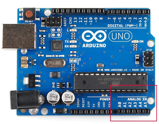
In this tutorial we are introducing concept of ADC (Analog to Digital Conversion) in ARDUINO UNO. Arduino board has six ADC channels, as show in figure below. Among those any one or all of them can be used as inputs for analog voltage. The Arduino Uno ADC is of 10 bit resolution (so the integer values from (0-(2^10) 1023)). This means that it will map input voltages between 0 and 5 volts into integer values between 0 and 1023. So for every (5/1024= 4.9mV) per unit.
Description:
An Analog to Digital Converter (ADC) is a very useful feature that converts an analog voltage on a pin to a digital number. By converting from the analog world to the digital world, we can begin to use electronics to interface to the analog world around us.Not every pin on a microcontroller has the ability to do analog to digital conversions. On the Arduino board, these pins have an ‘A’ in front of their label (A0 through A5) to indicate these pins can read analog voltages.ADCs can vary greatly between microcontroller. The ADC on the Arduino is a 10-bit ADC meaning it has the ability to detect 1,024 (210) discrete analog levels. Some microcontrollers have 8-bit ADCs (28 = 256 discrete levels) and some have 16-bit ADCs (216 = 65,536 discrete levels).The way an ADC works is fairly complex. There are a few different ways to achieve this feat (see Wikipedia for a list), but one of the most common technique uses the analog voltage to charge up an internal capacitor and then measure the time it takes to discharge across an internal resistor. The microcontroller monitors the number of clock cycles that pass before the capacitor is discharged. This number of cycles is the number that is returned once the ADC is complete.
An Analog to Digital Converter (ADC) is a very useful feature that converts an analog voltage on a pin to a digital number. By converting from the analog world to the digital world, we can begin to use electronics to interface to the analog world around us.
Not every pin on a microcontroller has the ability to do analog to digital conversions. On the Arduino board, these pins have an ‘A’ in front of their label (A0 through A5) to indicate these pins can read analog voltages.
ADCs can vary greatly between microcontroller. The ADC on the Arduino is a 10-bit ADC meaning it has the ability to detect 1,024 (210) discrete analog levels. Some microcontrollers have 8-bit ADCs (28 = 256 discrete levels) and some have 16-bit ADCs (216 = 65,536 discrete levels).
The way an ADC works is fairly complex. There are a few different ways to achieve this feat (see Wikipedia for a list), but one of the most common technique uses the analog voltage to charge up an internal capacitor and then measure the time it takes to discharge across an internal resistor. The microcontroller monitors the number of clock cycles that pass before the capacitor is discharged. This number of cycles is the number that is returned once the ADC is complete.
Relating ADC Value to Voltage
The ADC reports a ratiometric value. This means that the ADC assumes 5V is 1023 and anything less than 5V will be a ratio between 5V and 1023.Analog to digital conversions are dependant on the system voltage. Because we predominantly use the 10-bit ADC of the Arduino on a 5V system, we can simplify this equation slightly:If your system is 3.3V, you simply change 5V out with 3.3V in the equation. If your system is 3.3V and your ADC is reporting 512, what is the voltage measured? It is approximately 1.65V.If the analog voltage is 2.12V what will the ADC report as a value?Rearrange things a bit and we get:Ahah! The ADC should report 434.Block Diagram
The ADC reports a ratiometric value. This means that the ADC assumes 5V is 1023 and anything less than 5V will be a ratio between 5V and 1023.
Analog to digital conversions are dependant on the system voltage. Because we predominantly use the 10-bit ADC of the Arduino on a 5V system, we can simplify this equation slightly:
If your system is 3.3V, you simply change 5V out with 3.3V in the equation. If your system is 3.3V and your ADC is reporting 512, what is the voltage measured? It is approximately 1.65V.
If the analog voltage is 2.12V what will the ADC report as a value?
Rearrange things a bit and we get:
Ahah! The ADC should report 434.

Schematic
Code
// ****************************************************
// Poject: Interfacing ADC to Arduino
// Author: Hack Projects India
// Module description: Operate MAX232
// ****************************************************
void setup() {
  // initialize serial communication at 9600 bits per second:
  Serial.begin(9600);
}

// the loop routine runs over and over again forever:
void loop() {
  // read the input on analog pin 0:
  int sensorValue = analogRead(A0);
  // Convert the analog reading (which goes from 0 - 1023) to a voltage (0 - 5V):
  float voltage = sensorValue * (5.0 / 1023.0);
  // print out the value you read:
  Serial.println(voltage);
}


No comments:
Post a Comment