Aim:
In this tutorial, we are going to discuss the interfacing of external ADC0808/9 with 8051.
We will be reading the ADC values from channel Zero.
In this tutorial, we are going to discuss the interfacing of external ADC0808/9 with 8051.
We will be reading the ADC values from channel Zero.
We will be reading the ADC values from channel Zero.
Description:

ADC-0808/9
8051 does not have the inbuilt ADC and we will be using the external
8-bit ADC ie. ADC0808/ADC0809. ADC0809 is an 8-bit Successive
Approximation ADC which is multiplexed among 8 input pins.
The A/D module has high and low-voltage reference input that can be set
using the pins Vref+ and Vref- as shown in the below image. With 5v as
the Vref+ and 0v as Vref- the resolution of ADC0809 can be determined as
below: $$resolution of ADC = ((Vref+) – (Vref-))/(2^{8}-1) = 5/255
=0.0196 = 19.6mv$$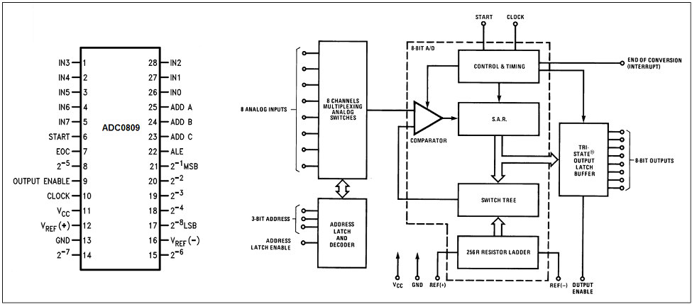
8051 does not have the inbuilt ADC and we will be using the external
8-bit ADC ie. ADC0808/ADC0809. ADC0809 is an 8-bit Successive
Approximation ADC which is multiplexed among 8 input pins.
The A/D module has high and low-voltage reference input that can be set using the pins Vref+ and Vref- as shown in the below image. With 5v as the Vref+ and 0v as Vref- the resolution of ADC0809 can be determined as below: $$resolution of ADC = ((Vref+) – (Vref-))/(2^{8}-1) = 5/255 =0.0196 = 19.6mv$$
The A/D module has high and low-voltage reference input that can be set using the pins Vref+ and Vref- as shown in the below image. With 5v as the Vref+ and 0v as Vref- the resolution of ADC0809 can be determined as below: $$resolution of ADC = ((Vref+) – (Vref-))/(2^{8}-1) = 5/255 =0.0196 = 19.6mv$$

ADC Pins
Lets see the pins of the ADC0809
- Addres Lines(A,B,C): As
mentioned earlier, ADC0809 has 8-muliplexed ADC channels. A particular
input channel is selected by using these address bits as shown below.
C B A SELECTED ADC CHANNEL 0 0 0 INO 0 0 1 IN1 0 1 0 IN2 0 1 1 IN3 1 0 0 IN4 1 0 1 IN5 1 1 0 IN6 1 1 1 IN7
- Address Latch Enable (ALE): A low-to-high signal at this pin will latch the above-selected address and selected the respective channel for ADC conversion.
- START Conversion (SOC): The
A/D converter’s successive approximation register (SAR) is reset on the
positive edge of the start conversion (SC) pulse. Thus we need to
generate a LOW-HIGH-LOW pulse for starting the ADC conversion.
- End of Conversion (EOC): Once
the conversion is over, this pin is pulled HIGH by ADC0809. This pin
needs to be monitored for the conversion to complete and then read the
data.
- Output Enable(OE): ADC0809
does the adc conversion and holds the data in the internal registers. A
HIGH signal on this pin will bring the data on the output lines.

Lets see the pins of the ADC0809
- Addres Lines(A,B,C): As mentioned earlier, ADC0809 has 8-muliplexed ADC channels. A particular input channel is selected by using these address bits as shown below.
| C | B | A | SELECTED ADC CHANNEL |
|---|---|---|---|
| 0 | 0 | 0 | INO |
| 0 | 0 | 1 | IN1 |
| 0 | 1 | 0 | IN2 |
| 0 | 1 | 1 | IN3 |
| 1 | 0 | 0 | IN4 |
| 1 | 0 | 1 | IN5 |
| 1 | 1 | 0 | IN6 |
| 1 | 1 | 1 | IN7 |
- Address Latch Enable (ALE): A low-to-high signal at this pin will latch the above-selected address and selected the respective channel for ADC conversion.
- START Conversion (SOC): The A/D converter’s successive approximation register (SAR) is reset on the positive edge of the start conversion (SC) pulse. Thus we need to generate a LOW-HIGH-LOW pulse for starting the ADC conversion.
- End of Conversion (EOC): Once the conversion is over, this pin is pulled HIGH by ADC0809. This pin needs to be monitored for the conversion to complete and then read the data.
- Output Enable(OE): ADC0809 does the adc conversion and holds the data in the internal registers. A HIGH signal on this pin will bring the data on the output lines.

Pin Connections
You can connect the ADC0809 to any of the PORT pins available on your boards and update this section accordingly.
PIN
Name
Function
Connection with AVR PIN
1 ADD-A ADD Chanel A P2.0 2 ADD-B ADD Chanel B P2.1 3 ADD-C ADD Chanel C P2.2 4 CLOCK Clock P2.3 5 ALE Address Latch Enable P2.4 6 OE Output Enable P2.5 7 START Start P2.6 8 EOC End Of Cycle P2.7 9 D0 DATA OUT P0.7 10 D1 DATA OUT P0.6 11 D2 DATA OUT P0.5 12 D3 DATA OUT P0.4 13 D4 DATA OUT P0.3 14 D5 DATA OUT P0.2 15 D6 DATA OUT P0.1 16 D7 DATA OUT P0.0
You can connect the ADC0809 to any of the PORT pins available on your boards and update this section accordingly.
PIN
|
Name
|
Function
|
Connection with AVR PIN
|
| 1 | ADD-A | ADD Chanel A | P2.0 |
| 2 | ADD-B | ADD Chanel B | P2.1 |
| 3 | ADD-C | ADD Chanel C | P2.2 |
| 4 | CLOCK | Clock | P2.3 |
| 5 | ALE | Address Latch Enable | P2.4 |
| 6 | OE | Output Enable | P2.5 |
| 7 | START | Start | P2.6 |
| 8 | EOC | End Of Cycle | P2.7 |
| 9 | D0 | DATA OUT | P0.7 |
| 10 | D1 | DATA OUT | P0.6 |
| 11 | D2 | DATA OUT | P0.5 |
| 12 | D3 | DATA OUT | P0.4 |
| 13 | D4 | DATA OUT | P0.3 |
| 14 | D5 | DATA OUT | P0.2 |
| 15 | D6 | DATA OUT | P0.1 |
| 16 | D7 | DATA OUT | P0.0 |
Block Diagram

Schematic

Code
// ****************************************************
// Poject: Interfacing ADC to 8051 microcontroller
// Author: Code Bloges
// Module description: Operate array of LED's
// ****************************************************
#include <reg51.h>
#define Baud_rate 0xFD  // BAUD RATE 9600
sbit ADD_A = P2^0;
sbit ADD_B = P2^1;
sbit ADD_C = P2^2;
sbit clk= P2^3;      //for clock
sbit ALE = P2^4;     //adress latch enable
sbit OE = P2^5;                   //output enable
sbit SC = P2^6;   //start convertion
sbit EOC = P2^7;   //end convertion
sfr input=0x80;  //0x80 is the adress of port 0 of 8051,it act as a sensor o/p & microcontroller i/p
//function prototype
void channel_selection(unsigned char channel);
unsigned char read_adc(unsigned char channel_area);
void USART_Init(void);
void USART_Transmit(unsigned char);
void delay(unsigned int dly);
void delay(unsigned int dly)
{
 unsigned int i,j;
 for (i=dly;i>0;i--)
 for(j=0;j<122;j++);
}
void timer0() interrupt 1  // Function to generate clock of frequency 500KHZ using Timer 0 interrupt.
{
clk=~clk;
}
void channel_selection(unsigned char channel)
{
                if(channel==0)
                {
                                ADD_C=0;  ADD_B=0;ADD_A=0;
                }
                else if(channel==1)
                {
                                ADD_C=0;  ADD_B=0;ADD_A=1;
                }
                else if(channel==2)
                {
                                ADD_C=0;  ADD_B=1;ADD_A=0;
                }
                else if(channel==3)
                {
                                ADD_C=0;  ADD_B=1;ADD_A=1;
                }
                else if(channel==4)
                {
                                ADD_C=1;  ADD_B=0;ADD_A=0;
                }
                else if(channel==5)
                {
                                ADD_C=1;  ADD_B=0;ADD_A=1;
                }
                else if(channel==6)
                {
                                ADD_C=1;  ADD_B=1;ADD_A=0;
                }
                else
                {
                                ADD_C=1;  ADD_B=1;ADD_A=1;
                }
}
unsigned char read_adc(unsigned char channel_area)
  {
   unsigned char ch=0;
                channel_selection(channel_area);
                EOC=1; //end of convertion high
                 OE=0;   //output enable low
                ALE=0;  //adress latch enable low
                delay(2);
                ALE = 1;    //ALE high
                delay(2);
                SC=0;      //start convertion  pin low
                delay(2);
                SC = 1;   //start convertion pin high
                delay(2);
                ALE = 0;  //adress latch enable low
                delay(2);
                SC = 0;   //start convertion  pin low
                while(EOC==1);                //wait for EOC pin is high
    OE = 1;
    delay(2);
                ch=input;
    OE = 0;
                return  (ch);
                }
void USART_Init(void)                              // INITIALIZE SERIAL PORT
{
                TMOD = 0x20;                           // Timer 1 IN MODE 2 -AUTO RELOAD TO GENERATE BAUD RATE
                SCON = 0x50;                                                    // SERIAL MODE 1, 8-DATA BIT 1-START BIT, 1-STOP BIT, REN ENABLED
                TH1 = Baud_rate;                                            // LOAD BAUDRATE TO TIMER REGISTER
                TR1 = 1;                                                                   // START TIMER
}
void USART_Transmit(unsigned char serialdata)
{
                SBUF = serialdata;                                                        // LOAD DATA TO SERIAL BUFFER REGISTER
                while(TI == 0);                                                   // WAIT UNTIL TRANSMISSION TO COMPLETE
                TI = 0;                                                                                    // CLEAR TRANSMISSION INTERRUPT FLAG
}
void Convert_Transmit(int val,unsigned int field_length)
{
                char str[5]={0,0,0,0,0};
                int i=4,j=0;
                while(val)
                {
                str[i]=val%10;
                val=val/10;
                i--;
                }
                if(field_length==-1)
                                while(str[j]==0) j++;
                else
                                j=5-field_length;
                if(val<0) USART_Transmit('-');
                for(i=j;i<5;i++)
                {
                USART_Transmit(48+str[i]);
                }
}
void main()
{
                unsigned int y,z;
                USART_Init();
                input=0xff;         //as port 0 bydefult low we have to made as high
                TMOD=0x22;  //timer0 setting for generating clock of 500KHz using interrupt enable mode.
                TH0=0xFD;
                IE=0x82;
                TR0=1;
                while(1)
                {
                                   y=read_adc(7);              //huminity sensor
                                   z=read_adc(6);  //tempareture sensor
                                   y=y*1.95;
                                   z=z*1.95;
                       delay(25);
                                   USART_Transmit('P');
                                   Convert_Transmit(y,4);
                                   USART_Transmit('\r');
                                   USART_Transmit('E');
                                   Convert_Transmit(z,4);
                                   USART_Transmit('\r');
                                   delay(25);
                }
}
// ****************************************************
// Poject: Interfacing ADC to 8051 microcontroller
// Author: Code Bloges
// Module description: Operate array of LED's
// ****************************************************
#include <reg51.h>
#define Baud_rate 0xFD // BAUD RATE 9600
sbit ADD_A = P2^0;
sbit ADD_B = P2^1;
sbit ADD_C = P2^2;
sbit clk= P2^3; //for clock
sbit ALE = P2^4; //adress latch enable
sbit OE = P2^5; //output enable
sbit SC = P2^6; //start convertion
sbit EOC = P2^7; //end convertion
sfr input=0x80; //0x80 is the adress of port 0 of 8051,it act as a sensor o/p & microcontroller i/p
//function prototype
void channel_selection(unsigned char channel);
unsigned char read_adc(unsigned char channel_area);
void USART_Init(void);
void USART_Transmit(unsigned char);
void delay(unsigned int dly);
void delay(unsigned int dly)
{
unsigned int i,j;
for (i=dly;i>0;i--)
for(j=0;j<122;j++);
}
void timer0() interrupt 1 // Function to generate clock of frequency 500KHZ using Timer 0 interrupt.
{
clk=~clk;
}
void channel_selection(unsigned char channel)
{
if(channel==0)
{
ADD_C=0; ADD_B=0;ADD_A=0;
}
else if(channel==1)
{
ADD_C=0; ADD_B=0;ADD_A=1;
}
else if(channel==2)
{
ADD_C=0; ADD_B=1;ADD_A=0;
}
else if(channel==3)
{
ADD_C=0; ADD_B=1;ADD_A=1;
}
else if(channel==4)
{
ADD_C=1; ADD_B=0;ADD_A=0;
}
else if(channel==5)
{
ADD_C=1; ADD_B=0;ADD_A=1;
}
else if(channel==6)
{
ADD_C=1; ADD_B=1;ADD_A=0;
}
else
{
ADD_C=1; ADD_B=1;ADD_A=1;
}
}
unsigned char read_adc(unsigned char channel_area)
{
unsigned char ch=0;
channel_selection(channel_area);
EOC=1; //end of convertion high
OE=0; //output enable low
ALE=0; //adress latch enable low
delay(2);
ALE = 1; //ALE high
delay(2);
SC=0; //start convertion pin low
delay(2);
SC = 1; //start convertion pin high
delay(2);
ALE = 0; //adress latch enable low
delay(2);
SC = 0; //start convertion pin low
while(EOC==1); //wait for EOC pin is high
OE = 1;
delay(2);
ch=input;
OE = 0;
return (ch);
}
void USART_Init(void) // INITIALIZE SERIAL PORT
{
TMOD = 0x20; // Timer 1 IN MODE 2 -AUTO RELOAD TO GENERATE BAUD RATE
SCON = 0x50; // SERIAL MODE 1, 8-DATA BIT 1-START BIT, 1-STOP BIT, REN ENABLED
TH1 = Baud_rate; // LOAD BAUDRATE TO TIMER REGISTER
TR1 = 1; // START TIMER
}
void USART_Transmit(unsigned char serialdata)
{
SBUF = serialdata; // LOAD DATA TO SERIAL BUFFER REGISTER
while(TI == 0); // WAIT UNTIL TRANSMISSION TO COMPLETE
TI = 0; // CLEAR TRANSMISSION INTERRUPT FLAG
}
void Convert_Transmit(int val,unsigned int field_length)
{
char str[5]={0,0,0,0,0};
int i=4,j=0;
while(val)
{
str[i]=val%10;
val=val/10;
i--;
}
if(field_length==-1)
while(str[j]==0) j++;
else
j=5-field_length;
if(val<0) USART_Transmit('-');
for(i=j;i<5;i++)
{
USART_Transmit(48+str[i]);
}
}
void main()
{
unsigned int y,z;
USART_Init();
input=0xff; //as port 0 bydefult low we have to made as high
TMOD=0x22; //timer0 setting for generating clock of 500KHz using interrupt enable mode.
TH0=0xFD;
IE=0x82;
TR0=1;
while(1)
{
y=read_adc(7); //huminity sensor
z=read_adc(6); //tempareture sensor
y=y*1.95;
z=z*1.95;
delay(25);
USART_Transmit('P');
Convert_Transmit(y,4);
USART_Transmit('\r');
USART_Transmit('E');
Convert_Transmit(z,4);
USART_Transmit('\r');
delay(25);
}
}
Downloads:
The code was compiled in Keil uvision4 and simulation was made in Proteus v7.7.
To download code and proteus simulation click here.
Further Reading suggestions:
You may also like,
- Interfacing keypad with 8051
- Interfacing DAC with 8051
- Interfacing with UART of 8051 controller
- Interfacing SPI communication with 8051
- 8051 Displaying Custom Characters on LCD
- 8051 Graphical LCD
- RTC interfacing using I2C in 8051
- Interfacing ultrasonic sensor with 8051
- Interfacing GPS Modu with 8051
- Interfacing GSM Module with 8051
- Interfacing PWM in 8051
No comments:
Post a Comment