Aim:
In this article I will describe how to interface a Ultrasonic Range Finder Module with a PIC18F4520 microcontroller. I will provide a HEX file which you can burn into your PIC18F4520 directly to quickly test this whole setup.

Description:
We know that sound vibrations can not penetrate through solids. So what happens is, when a source of sound generates vibrations they travel through air at a speed of 220 meters per second. These vibrations when they meet our ear we describe them as sound. As said earlier these vibrations can not go through solid, so when they strike with a surface like wall, they are reflected back at the same speed to the source, which is called echo.
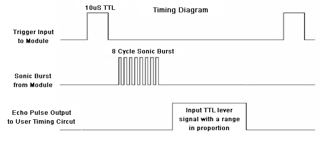
Ultrasonic sensor “HC-SR04” provides an output signal proportional to distance based on the echo. The sensor here generates a sound vibration in ultrasonic range upon giving a trigger, after that it waits for the sound vibration to return. Now based on the parameters, sound speed (220m/s) and time taken for the echo to reach the source, it provides output pulse proportional to distance.

As shown in figure, at first we need to initiate the sensor for measuring distance, that is a HIGH logic signal at trigger pin of sensor for more than 10uS, after that a sound vibration is sent by sensor, after a echo, the sensor provides a signal at the output pin whose width is proportional to distance between source and obstacle.
Block Diagram

Schematic
Code
// ******************************************************
// Project: Ultrasonic sensor using PIC18F4520
// Author: Hack Projects India
// Module description: Operate ultrasonic sensor
// ******************************************************
#include <p18f4520.h>
#include <delays.h>
#pragma config OSC=HS, FCMEN=ON, WDT=OFF, IESO=OFF, XINST=OFF, LVP=OFF
#define lcd PORTD
unsigned char rs,en;
unsigned int d;

void cmd_lcd(unsigned char z)
{
  rs=0x00;//for command
  en=0x08;//en high
  lcd=((z)&0xf0)|en|rs;
  Delay10TCYx(10);
  en=0x00;//en low
  lcd=((z)&0xf0)|en|rs;
  en=0x08;//en high
  lcd=((z<<4)&0xf0)|en|rs;
  Delay10TCYx(10);
  en=0x00;//en low
  lcd=((z<<4)&0xf0)|en|rs;
}
void data_lcd(unsigned char z)
{
     rs=0x04 ;//for data
     en=0x08;//en high
     lcd=((z)&0xf0)|en|rs;
     Delay10TCYx(10);
     en=0x00;//en low
     lcd=((z)&0xf0)|en|rs;
     en=0x08;//en high
     lcd=((z<<4)&0xf0)|en|rs;
     Delay10TCYx(10);
     en=0x00;//en low
     lcd=((z<<4)&0xf0)|en|rs;
}
void init_lcd()
{
     cmd_lcd(0x02);//4bit mode
     cmd_lcd(0x06);//entry mode
     cmd_lcd(0x0c);//diply on cr off
     cmd_lcd(0x28);//4 bit
}
void LCDWriteInt(int val,unsigned int field_length)
{
 char str[5]={0,0,0,0,0};
 int i=4,j=0;
 while(val)
 {
 str[i]=val%10;
 val=val/10;
 i--;
 }
 j=5-field_length;
 if(val<0) data_lcd(' ');
 for(i=j;i<5;i++)
 {
 data_lcd(48+str[i]);
 }
}

void LCDWriteString(unsigned char *str)
{
 while((*str)!='\0')
 {
  data_lcd(*str);
  str++;
 }
}
void main()
{
    int a;
    ADCON1=0b00001111;
    TRISA=0Xff;
    TRISD=0;  // Configure Port d as output port
    TRISB=0;  // Configure Port B as output port
    init_lcd();

    TRISB = 0b00010000;           //RB4 as Input PIN (ECHO)
    cmd_lcd(0x01);

    T1CON = 0x10;                 //Initialize Timer Module
    while(1)
    {

    TMR1H = 0;                //Sets the Initial Value of Timer
    TMR1L = 0;                //Sets the Initial Value of Timer

    PORTBbits.RB0 = 1;                  //TRIGGER HIGH
    Delay10TCYx(10);           //10uS Delay
    PORTBbits.RB0 = 0;                  //TRIGGER LOW

    while(!PORTBbits.RB4);              //Waiting for Echo
    T0CONbits.TMR0ON =1;               //Timer Starts
    while(PORTBbits.RB4);               //Waiting for Echo goes LOW
    T0CONbits.TMR0ON =0;               //Timer Stops

    a = (TMR1L | (TMR1H<<8)); //Reads Timer Value
    a = a/58.82;              //Converts Time to Distance
    a = a + 1;                //Distance Calibration
    if(a>=2 && a<=400)        //Check whether the result is valid or not
    {
      cmd_lcd(0x80);
      LCDWriteString("Distance = ");

      cmd_lcd(0xc0);
      LCDWriteInt(a,4);
      LCDWriteString("cm");
    }
    else
    {
      cmd_lcd(0x01);
      LCDWriteString("Out of Range");
    }
    Delay10TCYx(400);
    }
}
Downloads:
The code was compiled in Keil uvision4 and simulation was made in Proteus v7.7.
To download code and proteus simulation click here.
Further Reading suggestions:
You may also like,
- Interfacing keypad with PIC
- nterfacing DAC with PIC
- Interfacing with UART of PIC controller
- Interfacing SPI communication with PIC
- PIC Displaying Custom Characters on LCD
- PIC Graphical LCD
- RTC interfacing using I2C in PIC
- Interfacing GPS Modu with PIC
- Interfacing GSM Module with PIC
- Interfacing PWM in PIC
- Interfacing ADC with PIC
- Scrolling string on LCD using PIC

No comments:
Post a Comment