Aim:
In this tutorial, we are going to discuss the serial/UART communication of PIC18F4520. After understating the basics of PIC18F4520 UART module, We will see how to use the ExploreEmbedded libraries to communicate with any of the UART devices.
Description:

UART stands for Universal Asynchronous Receiver / Transmitter. It is a very popular serial communication interface which provides Full Duplex communication between two devices. UART uses two data lines for sending (TX) and receiving (RX) data. Ground/Reference of both devices should be made common. As the name indicates it is an asynchronous communication interface, which means that it doesn’t need to send CLOCK along with data as in synchronous communications. UART is the communication interface used by our old computer’s RS-232 port.
Some of the Microchip’s PIC Microcontroller has built in USART Module. USART stands for Universal Synchronous Asynchronous Receiver Transmitter and it can be configured in following modes.
- UART – Asynchronous (Full Duplex)
- USRT Master – Synchronous (Half Duplex)
- USRT Slave – Synchronous (Half Duplex)
In this tutorial we will learn how to use UART Mode of USART Module using MPLAB XC8 Compiler. For demonstration we are using PIC 16F877A microcontroller.
PIC 18F4520 USART Module
USART Registers
TXSTA – Transmit Status and Control Register
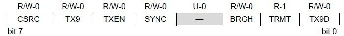
TXSTA – Transmit Status and Control Register
- Bit 0 TX9D : This is the 9th bit of data in the 9 bit transmission mode which is commonly used as a Parity Bit.
- Bit 1 TRMT : This is the Transmit Shift Register (TSR) status bit. This can be used to check whether the data written to transmit register is transmitted or not. When the TRS is empty this bit is set and when the TSR is full this bit will be 0.
- Bit 2 BRGH : This is the High Baud Rate Select bit for Asynchronous mode operation and is unused in Synchronous mode. Setting this bit selects High Speed and clearing this bit selects Low Speed baud rates. You will can see the baud rate calculation later in this article.
- Bit 3 Unimplemented : This bit is unimplemented and will read as 0.
- Bit 4 SYNC : This is the USART Mode select bit. Setting this bit selects Synchronous mode while clearing this bit selects Asynchronous mode.
- Bit 5 TXEN : Setting this bit enables the transmission. In the synchronous mode operation CREN and SREN bits of RCSTA register overrides this bit.
- Bit 6 TX9 : When this bit is set it enables the 9 bit transmission otherwise 8 bit transmission is used. 9th bit in the 9 bit transmission mode is commonly used as parity bit.
- Bit 7 CSRC : Clock Source Select Bit, this bit has no application in the Asynchronous mode operation of USART module. It is used to select master or slave mode in Synchronous mode operation.
RCSTA – Receive Status and Control Register

RCSTA – Receive Status and Control Register
- Bit 0 RX9D : This is the 9th bit of Received Data and is commonly used as Parity Bit.
- Bit 1 OERR : Overrun Error bit. A high at this bit indicates that Overrun error has occured.
- Bit 2 FERR : Framing Error bit. 1 at this bit stands for Framing Error while 0 stands for No Framing Error.
- Bit 3 ADDEN : Address Detect Enable bit. This bit is applicable only in Asynchronous 9 bit mode. Setting this bit enables Address Detect.
- Bit 4 CREN : Continuous Receive Enable bit. Setting this bit will enable Continuous Receive. In the Synchronous Mode CREN overrides SREN.
- Bit 5 SREN : Single Receive Enable bit. This bit has no effect on Asynchronous mode and Synchronous Slave mode. Setting this bit will enables Single Receive. This bit will cleared after the reception is complete.
- Bit 6 RX9 : Setting this bit enables 9 bit reception otherwise it will be in 8 bit reception mode.
- Bit 7 SPEN : Serial Port Enable bit. Setting this bit enables serial port and configures RC7, RC6 as serial port pins.
USART Baud Rate Generator (BRG)
Baud Rate Generator provides the required clock for the data transmission and reception. USART module has a dedicated 8 bit baud rate generator which supports both Synchronous and Asynchronous modes. The 8-bit SPBRG register controls the time period of this free running timer. In Asynchronous mode BRGH, 2nd bit of TXSTA register also controls the generated baud rate but in Synchronous mode it is ignored. Baud Rate can be calculated from the following equations, where FOSC is the clock frequency of the microcontroller.
Block Diagram

Schematic

Code
// *****************************************************
// Project: Serial UART communication using 8051
// Author: Hack Projects India
// Module description: Operate max232
// *****************************************************
#include<p18f452.h>
void txd(unsigned char ch);
unsigned char rxd();

void USART_Init()
{
    SPBRG =0x19;            // 9600 bps at XTA=4MHZ
    TXSTA=0X24;             // Transmission part enable
    RCSTA=0x90;             // Receiving part enable
}
void txd(unsigned char ch)

{
    TXREG=ch;               // Character send through transmission register
    while(!PIR1bits.TXIF);  // Upto transmitting character
}

unsigned char rxd()
{
    while(!PIR1bits.RCIF);  // Upto receiving character
    return RCREG;           // Return the character to main
}

void main()
{
    char c;
    USART_Init();
    while(1)
    {
        c = rxd();
        txd(c);
    }
}
Downloads:
The code was compiled in Keil uvision4 and simulation was made in Proteus v7.7.
To download code and proteus simulation click here.
Further Reading suggestions:
You may also like,
- Interfacing keypad with PIC
- nterfacing DAC with PIC
- Interfacing SPI communication with PIC
- PIC Displaying Custom Characters on LCD
- PIC Graphical LCD
- RTC interfacing using I2C in PIC
- Interfacing ultrasonic sensor with PIC
- Interfacing GPS Modu with PIC
- Interfacing GSM Module with PIC
- Interfacing PWM in PIC
- Interfacing ADC with PIC
- Scrolling string on LCD using PIC
No comments:
Post a Comment