Aim:
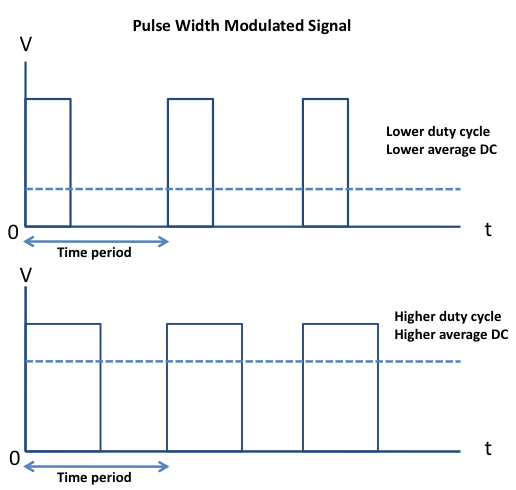
Pulse Width Modulation (PWM) is a comparatively recent power switching technique for providing intermediate amounts of electrical power between fully on and fully off levels. Usually, digital pulses have same on and off time period, but in some situations we need the digital pulse to have more/less on time/offtime. In PWM technique, we create digital pulses with unequal amount of on and off state to get required intermediate voltage values.
Description:
Pulse width modulation (PWM) is a technique of controlling the amount of power delivered to an electronic load using an on-off digital signal. The fraction of the period for which the signal is on is known as the duty cycle. The average DC value of the signal can be varied by varying the duty cycle. The duty cycle can be anywhere between 0 (signal is always off) to 1 (signal is constantly on). Suppose, if the signal has +5 V while it is on and 0 V during off condition, then by changing the duty cycle of the signal, any voltage between 0-5 V can be simulated. This method is commonly used for controlling speeds of DC motors and brightness of lamps. This lab session will talk about how to generate a PWM signal using the PIC18F4520 microcontroller.
PIC18F2420/2520/4420/4520 devices all have two CCP (Capture/Compare/PWM) modules. Each module contains a 16-bit register which can operate as a 16-bit Capture register, a 16-bit Compare register or a PWM Master/Slave Duty Cycle register. In 28-pin devices, the two standard CCP modules (CCP1 and CCP2) operate as described in this chapter. In 40/ 44-pin devices, CCP1 is implemented as an Enhanced CCP module with standard Capture and Compare
modes and Enhanced PWM modes. The ECCP implementation is discussed in Section 16.0 “Enhanced Capture/Compare/PWM (ECCP) Module”.
Capture Mode
In Capture mode, the CCPRxH:CCPRxL register pair captures the 16-bit value of the TMR1 or TMR3 register when an event occurs on the corresponding CCPx pin. An event is defined as one of the following:
- every falling edge
- every rising edge
- every 4th rising edge
- every 16th rising edge
The event is selected by the mode select bits, CCPxM<3:0> (CCPxCON<3:0>). When a capture is
made, the interrupt request flag bit, CCPxIF, is set; it must be cleared in software. If another capture occurs before the value in register CCPRx is read, the old captured value is overwritten by the new captured value.
Block Diagram

Schematic
Code
// ***********************************************
// Project: Interfacing PWM to PIC18F4520
// Author: Hack Projects India
// Module description: Operate Oscilloscope
// ***********************************************
#include<p18f4520.h>
#pragma config OSC=HS, FCMEN=ON, WDT=OFF, IESO=OFF, XINST=OFF, LVP=OFF

void SetPWMDutyCycle(unsigned char CCP, unsigned int DutyCycle);
void InitPWM(void);

void InitPWM(void)
{
 TRISCbits.RC1  = 0;     // Make CCP2 pin as output
 TRISCbits.RC2  = 0;              // Make CCP1 pin as output
 CCP1CON = 0x0C;           // Configure CCP1 module in PWM mode
 CCP2CON = 0x0C;           // Configure CCP2 module in PWM mode

 PR2   = 0xFF;             // Configure the Timer2 period
 T2CON = 0x01;             // Set Prescaler to be 4, hence PWM frequency is set to 10KHz.

 SetPWMDutyCycle(1, 0);    // Intialize the CCP1 PWM to 0 duty cycle
 SetPWMDutyCycle(2, 0);    // Intialize the CCP2 PWM to 0 duty cycle

 T2CON |= 0x04;            // Enable the Timer2, hence enable the PWM.
}


void SetPWMDutyCycle(unsigned char CCP, unsigned int DutyCycle)      // Give a value in between 0 and 255 for DutyCycle
{
 DutyCycle = 4*DutyCycle;    // 1023/255 is 4

 switch(CCP)
 {
 case 1:

  CCPR1L   = DutyCycle>>2;         // Put MSB 8 bits in CCPR1L
  CCP1CON &= 0xCF;                 // Make bit4 and 5 zero
  CCP1CON |= (0x30&(DutyCycle<<4));   // Assign Last 2 LSBs to CCP1CON
  break;

 }
}

void main(void)
{
 InitPWM();
 SetPWMDutyCycle(1,127);   //50% duty cycle
 while(1)
 {

 }
}
Downloads:
The code was compiled in Keil uvision4 and simulation was made in Proteus v7.7.
To download code and proteus simulation click here.
Further Reading suggestions:
You may also like,
- Interfacing keypad with PIC
- nterfacing DAC with PIC
- Interfacing with UART of PIC controller
- Interfacing SPI communication with PIC
- PIC Displaying Custom Characters on LCD
- PIC Graphical LCD
- RTC interfacing using I2C in PIC
- Interfacing ultrasonic sensor with PIC
- Interfacing GPS Modu with PIC
- Interfacing GSM Module with PIC
- Interfacing ADC with PIC
- Scrolling string on LCD using PIC


No comments:
Post a Comment