Aim:
Matrix Keypads are commonly used in calculators, telephones etc where a number of input switches are required. A keypad is a set of buttons arranged in a block or “pad” which usually bear digits, symbols and usually a complete set of alphabetical letters. If it mostly contains numbers then it can also be called a numeric keypad. Keypads are found on many alphanumeric keyboards and on other devices such as calculators, push-button telephones, combination locks, and digital door locks, which require mainly numeric input.

Description:
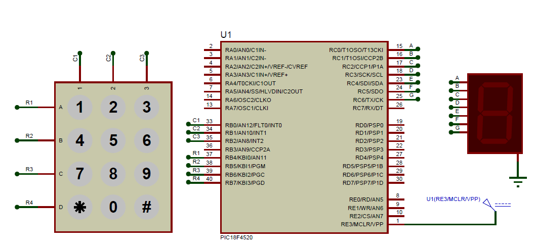
We know that matrix keypad is made by arranging push button switches in row and columns. In the straight forward way to connect a 4×4 keypad (16 switches) to a microcontroller we need 16 inputs pins. But by connecting switches in the following way we can read the status of each switch using 8 pins of the microcontroller.
The status of each keys can be determined by a process called Scanning. For the sake of explanation lets assume that all the column pins (Col1 – Col4) are connected to the inputs pins and all the row pins are connected to the output pins of the microcontroller. In the normal case all the column pins are pulled up (HIGH state) by internal or external pull up resistors. Now we can read the status of each switch through scanning.
- A logic LOW is given to Row1 and others (Row2 – Row-4) HIGH
- Now each Column is scanned. If any switch belongs to 1strow is pressed corresponding column will pulled down (logic LOW) and we can detect the pressed key.
- This process is repeated for all rows.
The keypad has 8 communication lines namely R1, R2, R3, R4, C1, C2, C3 and C4. R1 to R4 represents the four rows and C1 to C4 represents the four columns. When a particular key is pressed the corresponding row and column to which the terminals of the key are connected gets shorted. For example if key 1 is pressed row R1 and column C1 gets shorted and so on. The program identifies which key is pressed by a method known as column scanning. In this method a particular row is kept low (other rows are kept high) and the columns are checked for low. If a particular column is found low then that means that the key connected between that column and the corresponding row (the row that is kept low) is been pressed. For example if row R1 is initially kept low and column C1 is found low during scanning, that means key 1 is pressed.
Block Diagram
Schematic
Code
// *********************************************************
// Project: Interfacing keypad to PIC18F4520 microcontroller
// Author: Hack Projects India
// Module description: Operate keypad
// *********************************************************
#include<p18f452.h>
#pragma config OSC=HS, FCMEN=ON, WDT=OFF, IESO=OFF, XINST=OFF, LVP=OFF
void delay_ms(double ms);

void delay_ms(double ms)
{
 unsigned int i,j;
 for(i=0;i<ms;i++)
   for(j=0;j<10;j++);
}
int main()
{
    ADCON1=0xF0;
   TRISC=0x00;
   TRISB=0Xf0;
  while(1)
  {
   delay_ms(100);
    PORTB=1<<0;
 if(PORTBbits.RB4)
 {
  PORTC=0x06;
 }
 else if(PORTBbits.RB5)
 {
  PORTC=0x66;
 }
 else if(PORTBbits.RB6)
 {
  PORTC =0x07;
 }
 else if(PORTBbits.RB7)
 {
  PORTC=0x76;
 }
   delay_ms(100);
    PORTB=1<<1;
 if(PORTBbits.RB4)
 {
  PORTC=0x5b;
 }
 else if(PORTBbits.RB5)
 {
  PORTC=0x6d;
 }
 else if(PORTBbits.RB6)
 {
  PORTC=0x7f;
 }
 else if(PORTBbits.RB7)
 {
  PORTC=0x3f;
 }
   delay_ms(100);
    PORTB=1<<2;
 if(PORTBbits.RB4)
 {
  PORTC=0x4f;
 }
 else if(PORTBbits.RB5)
 {
  PORTC=0x7d;
 }
 else if(PORTBbits.RB6)
 {
  PORTC=0x6f;
 }
 else if(PORTBbits.RB7)
 {
  PORTC=0x76;
 }

  }
}
Downloads:
The code was compiled in Keil uvision4 and simulation was made in Proteus v7.7.
To download code and proteus simulation click here.
Further Reading suggestions:
You may also like,
- nterfacing DAC with PIC
- Interfacing with UART of PIC controller
- Interfacing SPI communication with PIC
- PIC Displaying Custom Characters on LCD
- PIC Graphical LCD
- RTC interfacing using I2C in PIC
- Interfacing ultrasonic sensor with PIC
- Interfacing GPS Modu with PIC
- Interfacing GSM Module with PIC
- Interfacing PWM in PIC
- Interfacing ADC with PIC
- Scrolling string on LCD using PIC


No comments:
Post a Comment